The first part of this upgrade is dealt with in another post on my blog
The Wanhao D7 has a lot of promise, but is let down badly by the pretty useless UV LED array – Due to the size, there is a pretty intense hotspot in the centre, while exposure drops off towards the edges of the build plate. This makes it impossible to get consistent results across the entire build plate.
Phrozen released the ParaLED upgrade, which is a full size replacement for the UV source. As it is a generic upgrade, I have produced a shroud which allows you to remove the fan from the ParaLED heatsink and mount it on the mounting already present on the base of the D7. This has an added advantage of giving a more even airflow over the heatsink and eliminating the dead spot caused by the fan hub. The shroud also positions the ParaLED at the correct distance from the LCD. The ParaLED is becoming difficult to find, but if you google it, you may come up with some still for sale
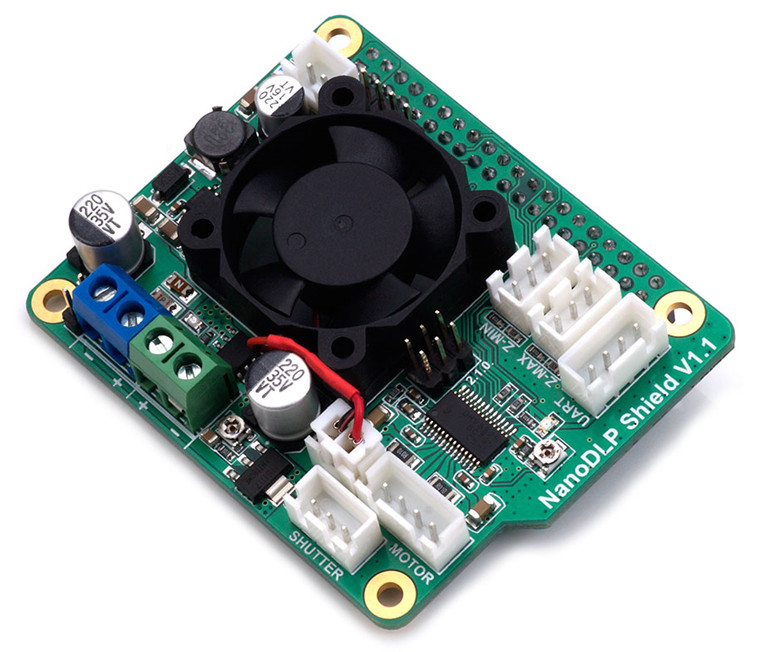
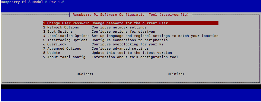
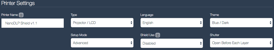
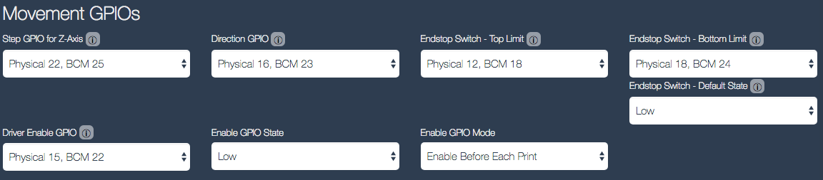
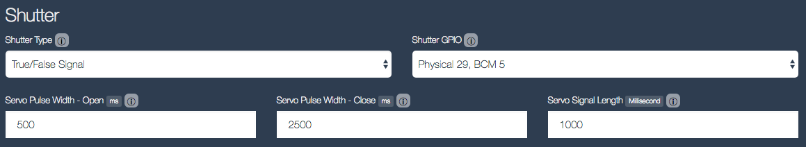
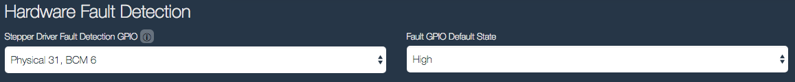
I have also removed the Wanhao board and replaced it with a Raspberry Pi running nanoDLP and a nanoDLP shield, making the machine stand-alone.
Finally, I have replaced the stepper motor, coupler and leadscrew with an integrated motor/leadscrew. This eliminates the inaccuracies caused by the coupler expanding and contracting.
Procedure for setting up the nanoDLP shield are documented in an earlier post. The STL files, nanoDLP Machine Profile, etc are supplied here on Thingiverse
I have used a 4.3″ Nextion. In case you want to use a different size screen (more easily supported by the nanoDLP/Nextion integration), I have included the SolidWorks part file for the front cover in the Thingiverse project so that you can adjust the cutout and mounting lugs to suit your screen. If you are using the 4.3 inch screen, I have created HMI and TFT files based on the HMI for the 3.2 inch screen, and included them in the Thingiverse project for you to use when setting up your Nextion screen
In addition to the D7, Nextion and ParaLED, you will need the following:
- An SSR-25 solid state relay – 3-32V DC input, 5-60V DC switching capability
- An optical endstop
- Plugs, pins and a crimp tool suitable for the on-board sockets of the shield
- Cable suitable for hooking everything up
- If you so desire, a Nema 17 stepper with integrated leadscrew (An adaptor is included in the printed parts if you want to do this)
The upgrade procedure is as follows:
1. Strip the D7. This is a ground-up rebuild
2. Print the parts. On the Base Extension, tap all 2.5mm diameter holes to M3. Leave the 3.5mm holes
3. Drill the original Wanhao steel base plate according to the drilling guide PDF
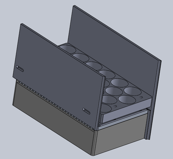
4. The back and left side of the ParaLED has aluminium plates attached. Remove and discard. Drill two holes in the front of the lens plate suitable for mounting the “Upper Shroud – Front” printed part. Remove the fan mounted to the ParaLED heatsink. Assemble the ParaLED to the “Shroud v2” part and attach the “Upper Shroud -Front” and “Upper Shroud – Rear” parts. The completed assembly is shown below:
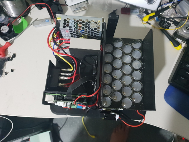
5. Mount a 60mm fan to the base plate, so that it draws in air from under the machine. It is advisable to fit a filter. Do not use any of the fans that came with the ParaLED, they are 24v and will not move air.
6. Mount the ParaLed Assembly to the base plate using 6 M4x10 screws. Make sure the fan wires exit through the cutout on the base of the shroud. Mount the “Base Extension v4” part to the base plate. Use 4 M3x10mm screws. Note that two of the screws which go through from the top, where the power socket plate used to mount and two go in from underneath. Screw on the rear feet through the base plate into the base extension using M3x14mm screws – You must drill out the rear feet mounting holes with a 3.5mm drill prior to assembly.
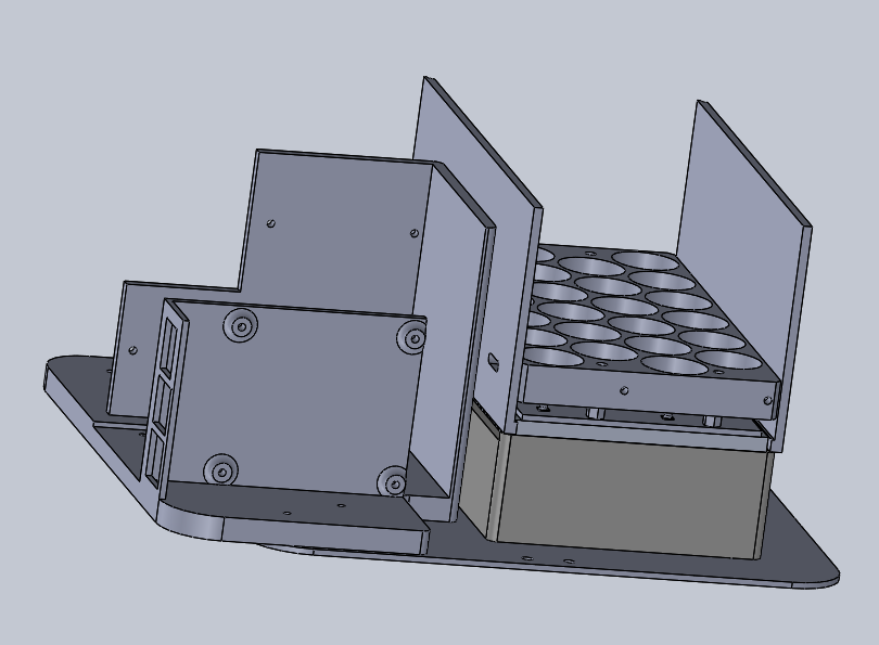
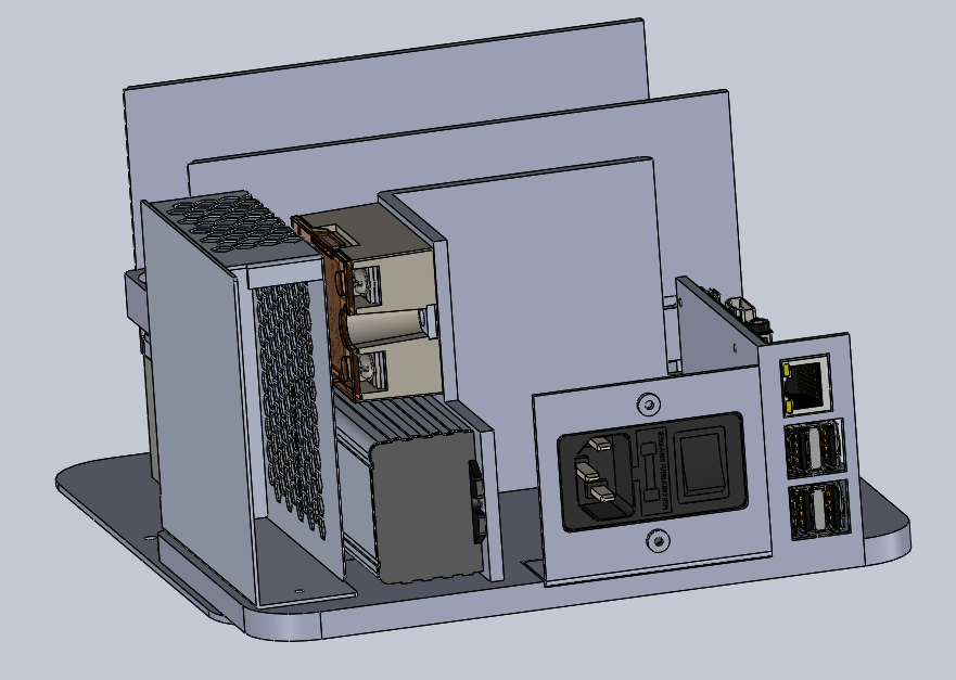
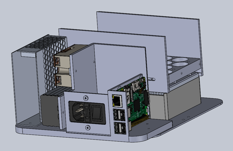
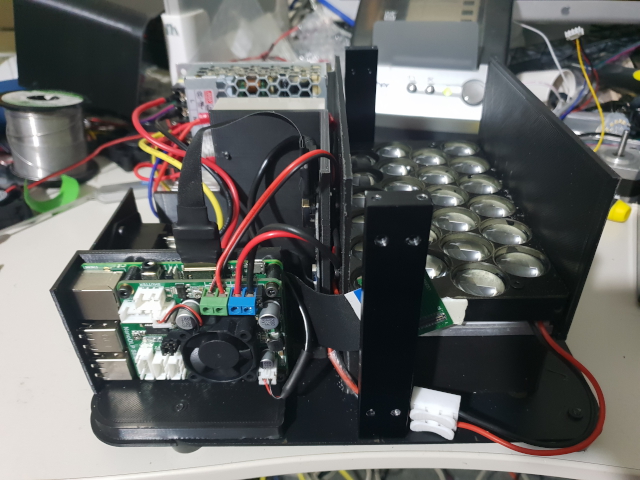
7. Mount the various bits and pieces (Excluding the HDMI/MIPI board) on the base extension. Use M3x18mm for the Raspberry Pi and shield (use the shield standoffs between the two), M3x6mm to mount the LED power unit and solid state relay and 1 M3x14mm and one M3x10mm to mount the PSU. Make sure you run an earth wire from the PSU earth screw to the 4mm hole you drilled and tapped on the base plate
8. Remove the USB and HDMI sockets from the rear bracket. Cut off the excess where the sockets used to be, so that the bracket only holds the power socket, and is 66mm wide. Mark and drill a mounting hole that will line up with the hole in the base extension. Mount the bracket on the base extension
9. Temporarily mount the top plate. Stick the MIPI/LCD adaptor board to the side of the ParaLED lens plate with double sided tape, ensuring that the MIPI cable socket faces the rear of the machine and that the LED ribbon cable is not under any strain. Stick the MIPI/HDMI board to the base extension using double sided tape, ensuring that there is no strain on the MIPI ribbon cable. When all is correct, unplug the LCD screen and remove the top plate
10. Cable everything up. I used a 10cm HDMI cable sourced from AliExpress and a Mini USB cable also sourced from AliExpress that I cut and crimped a plug onto which mates with the 5V out socket on the shield to power the MIPI board. The SSR is used to switch the LED constant current supply – do not switch this directly from the nanoDLP shield.
11. Attach the Nextion and a 60mm fan to the front cover and install the front cover. Do not use a fan from the ParaLED kit, they are 24v and will not move enough air – YOU WILL KILL YOUR LCD SCREEN IF YOU IGNORE THIS!
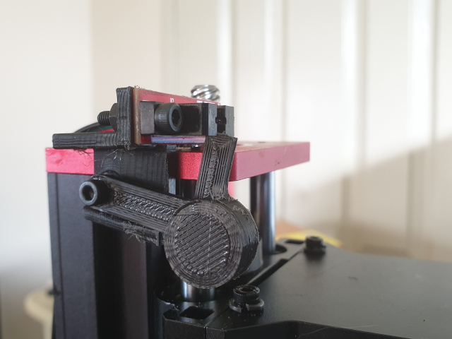
12. Install the fully assembled top cover (including motor, sensor, etc.)
13. Install the upper endstop to the top of the Z axis.
14. Attach the 60mm fan to the rear cover and install
Notes
1. This is intended for a v1.5 machine, or one that has been upgraded to v1.5
2. The intention is to run positive pressure in the case. All three fans should be blowing IN.
3. The maximum width fan that can fit in the rear cover is a 6010. you can use 6020s for the shroud and front cover fans
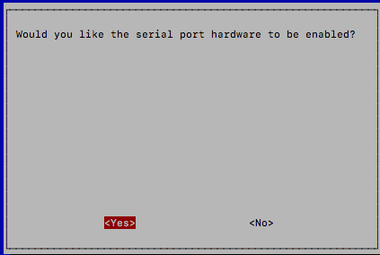
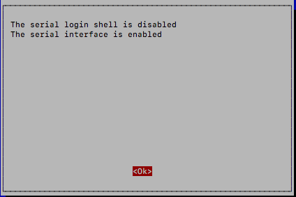
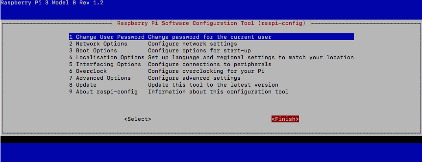
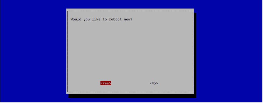
4. The motor driver on the shield must be set up according to instructions on my blog: https://collingwood.me.uk/blog/index.php/raspberry-pi-and-the-nanodlp-shield-v1-1/
5. The machine profile from this thing must be loaded
6. For resin profiles… Currently, you’re on your own. I’ll post any working ones I develop on this thing at a later stage, feel free to add working ones you develop in the comments
7. If anything goes wrong – you’re on your own. I’m not sitting in front of your machine, and I didn’t make any of the changes made to your machine. If you do not understand basic electronics and mechanics, do not attempt this.